
5December 2021
"The electronics assembly consists of the
switch, control board, battery terminal, and the LED work light. The assembly fixes problems such as a tool
that won't turn on, no longer has variable speed, has melted battery terminals, or the
LED light has burned out. Replacing the electronics assembly is a repair
that you can do yourself. I'm going to show you how. Hi, I'm Mark Sodja. Do it yourself repairs like these are easier
than you might think.
From lawn machines to cordless drills, kitchen
mixers, outdoor grills, our how-to videos walk you through each repair from start to
finish. Doing it yourself means never having to do
it alone. Let's get started. I'll begin by removing the front gear case. I'll remove the anvil from the gear case. Now remove half of the handle housing. There's a sticker at the rear of the housing
I'll cut in half. To remove the brush card, I'll lift the motor
assembly away from the housing. I'll pull the armature away from the brush
card. Now, I can remove the electronics assembly
from the housing. As I remove the battery terminal, I want to
be careful to not lose the compression spring behind it. I'll pull the electronics assembly away from
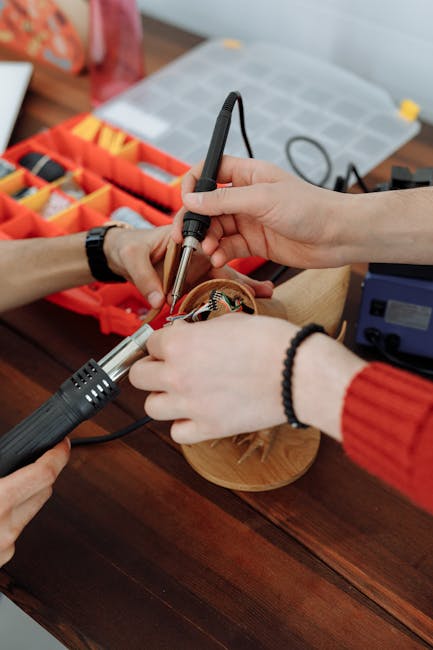
the housing. Now, I need to remove the brush card wiring
from the switch. I'll heat the solder connections with my soldering
gun. When the solder softens, I'll pull the wire
away from the switch.
Now, I can install the new switch. I'll start by re-soldering the wires from
the brush card. The black wire goes to the terminal labeled
M2 and the red wire to M1. I'll apply some soldering flux to give the
connections and then solder the wires. Now I can install the electronics assembly
back into the housing. I'll start by placing the LED light at the
front of the housing. I'll work the wires through the housing around
the shuttle, now reinstall the battery terminal. I'll place the compression spring in the recess
at the back of the terminal, compress the spring, and slide the terminal back into the
housing.
I'll place the circuit board back into the
housing. As I do this, I'm tucking the wires out of
the way. I'll line the switch with the housing, and
I'll make sure that the shuttle is connected to the post on the switch. Now I need to get the brush card ready to
reinstall the motor. I'll pull the brush out of the holder and
then set it off to the side. There's some grooves on the sides of the brush
holders to hold the spring. I'll pull the brushes back into the holders. Now I can slide the commutator into the brush
ring. I'll place the springs back over the brushes. Now, place the motor and gearbox assembly
back into the housing.
I'll line the notch on the field with the
tab on the gearbox. The notch and tab align with the housing and
lock into place. I'll make sure the switch, the circuit board,
terminal, and all the wires are tucked down into the housing. Now I can reinstall the other half of the
housing. Now, install the anvil onto the gearbox. I'll make sure I offset the ears on the anvil
with the hammers on the gearbox. I'll reinstall the gear case, sliding it over
the handle and aligning it with the housing. I'll secure it with the screws. That's all it takes to install a new electronics
assembly in your power tool. Be sure to check back often for new videos
and expert advice. If you found this video helpful, give us a
thumbs up and leave a comment.".